
How to Wire Driving / Fog Lights (www.mossmotors.com)
Driving lights and fog lights came about as car owners navigated the twisting turning by-ways of misty England. Powerful lighting was necessary to illuminate the road ahead for potential hazards to be successfully identified and avoided. In addition, foggy and wet conditions caused by road spray obliterated the edges of poorly crowned roads. There is one more oft-omitted benefit to driving lights and fog lights, simply stated they are “racer cool”; installing these lights, however,on your favorite British sports car takes planning and preparation.
I remember the days when I rummaged about in my “box of wires” and grabbed any gauge wire of sufficient or insufficient length, splicing together a “rat’s nest” of wire connections and crimped ends to connect any number of desired accessories. After a few smoke-filled incidents I am much more careful.
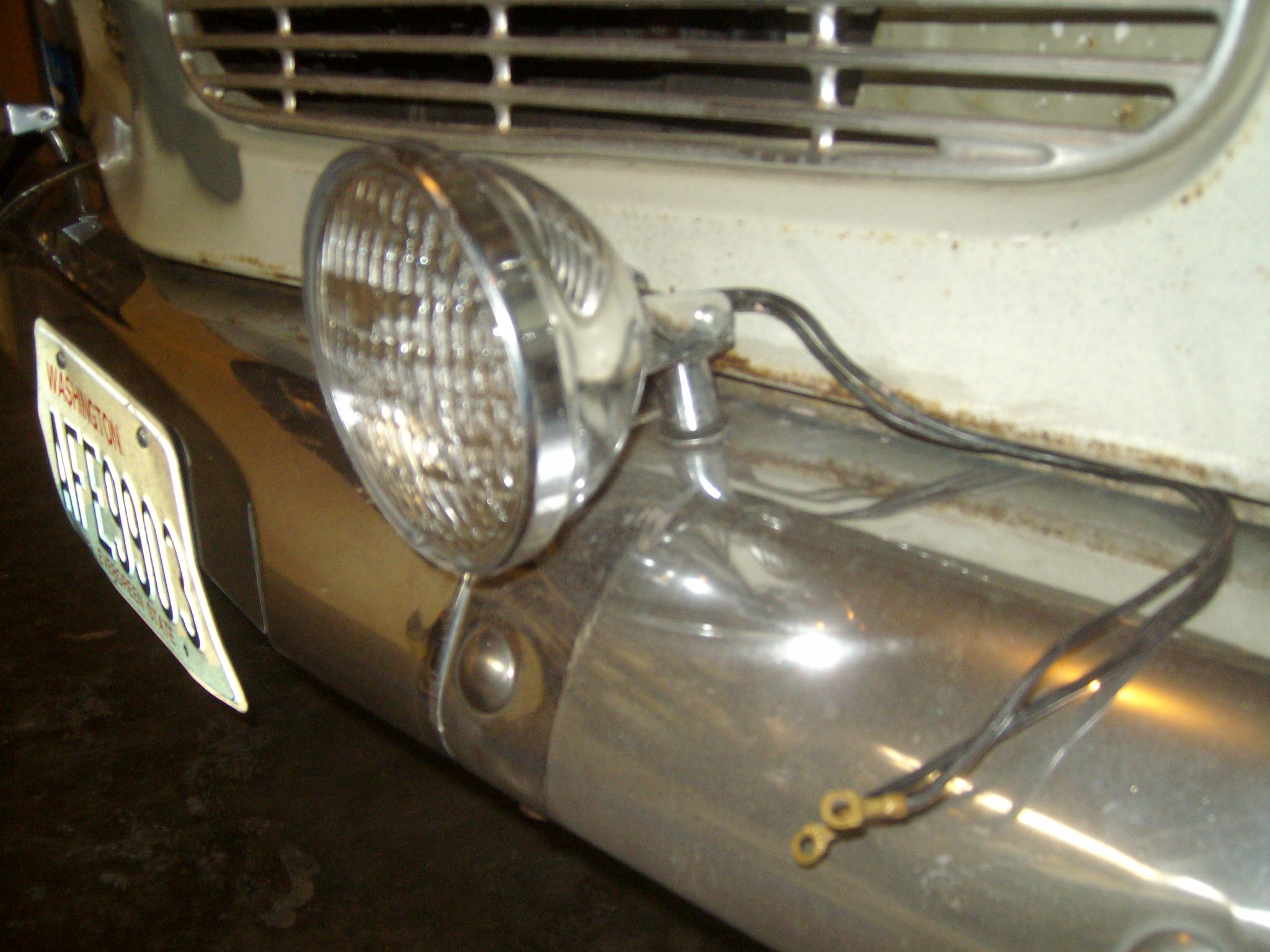
Let’s begin with your lights already mounted to the car, the wires dangling beneath or behind and waiting to receive power from Mr. Lucas. The first order of business is to determine the amperage of your driving/fog lights. My lamps are vintage and each unit reads 35 watts. The formula for amperage is watts divided by volts equals amps, or W/V=A. Since I will be wiring the lights to the relay with one lead, 70W/12V= 5.8A. I will be using 14-gauge wire, which handles up to 11.8A. Amps are a measure of current flow; volts are a measure of the force behind the flow of current. To protect my 14-gauge wiring I will be installing 10-amp inline fuses. The rule of thumb is this: the fuse ought to be rated near 80% of the amperage of the wire. This will ensure that you blow the fuse before you burn the wire. In my case, 80% of 11.8A is 9.44A so a 10-amp inline fuse is perfect.
I will need several colors of 14-gauge wire: black, green, white, and red. The reason is simple, the color identifies the purpose of each wire and if I ever have a problem I can track it down using my wiring diagram. Here is what I need to complete the job:
- Two 10-amp inline fuses (as above)
- Wire in the gauge and colors described
- Relay (with four male spade connectors on back)
- Switch (with three male spade connectors on back)
- Female spade connectors (crimp style)
- Eyelet connectors (crimp style)
- Butt connectors (crimp style)
- Electrical tape
- Lock ties (small black type)
- Crimping tool and cutter for wire
- Electric drill and a 7/64” drill bit
- Sheet metal screws (for connecting ground wires to body)

A tidy wiring diagram is a must.
Before cutting any wire, a good diagram is in order. Draw a diagram on plain white paper with wire gauge noted and colors identified. Each component must be labeled. This wiring diagram will stay with the car so make it neat and easily readable. Pictured is my wiring diagram for installing two fog lights with fuses, a switch, and a relay. If you need assistance drawing a diagram, refer to your car’s factory workshop manual [factory workshop manual??]. You’ll find examples of switches, lights, fuses—it’s helpful to understand and keep a universal language of the components in your drawings.
Relays are an important component in wiring fog or driving lights with a 30-60A draw. Basically, the relay protects the switch from getting hot and creating unwanted resistance. The low current through the switch triggers the relay to make a higher current connection to the heavy load of the fog lights. If you purchased your relay from a reputable source, it will have numbered terminals, which aid greatly in connecting everything correctly.
The fog lights are positioned first, the switch second, and the relay last. Since the switch will be on the dash and the fog lights at the front of the car, the only location decision to be made concerns the relay. I want the relay in a protected place near the front of the car. It needs to be near a 12V power source. I have chosen a position on the inner fender arch away from heat, but protected from road spray.
Use a test light to confirm your power sources for both the relay and the switch. I found a power source for my relay terminal number “30” on the low beam wire of the left headlight. I will splice into this wire so that my fog lights will work only when the low beams are on. I found a hot connection at the fuse block for the switch. Both of these 12V power lines need a 10-amp inline fuse.
Disconnect the battery!
Start with the ground connections for each component. Locate a suitable body connection point and drill a 7/64-inch hole in the body. Crimp an “eyelet” connector on the ground wire and screw a sheet metal screw through the “eyelet” and into the body. This must be done for the switch, the relay and each of the fog-lights. The relay ground terminal is numbered “85”.Now you are ready to run your wires according to the wiring diagram. Keep wires close to an existing wire loom and be careful of loops and sagging wires, which may snag on a moving component of the car. Do not add the crimped ends to any of the wires until all the wires are in place. Cut and leave about 6 inches of extra wire at every terminal point.
Drill the required hole in your dash for the switch; leave the switch free for the moment. I like to start wiring everything together at the switch and work my way toward the relay and the front of the car.
The switch has two remaining terminals. Connect a green wire from the “acc” terminal on the back of the switch to the number “86” terminal on the relay. The last terminal on the switch connects to the power source. This white wire will need a 10 amp inline fuse and is connected to the fuse block.
The relay is wired next. The power source for the relay is drawn from the low beam wire of the left headlight, as noted above. Splice a red wire from the headlight wire to the relay terminal “30.” This line needs a 10-amp inline fuse, so be sure and wire one in. The final terminal on the relay is numbered “87.” This terminal will carry power to the fog lights.
The fog lights each have two wires, one for ground and one for the 12V power. One of these wires from each fog light has already been connected to ground. A three-way connection must be made joining the second wire from each of the fog lights to the red wire going to the relay terminal “87.”
Finally, attach the switch to the dash and the relay to its location. A test is in order before you use the lock ties and button everything up.
Reconnect the battery
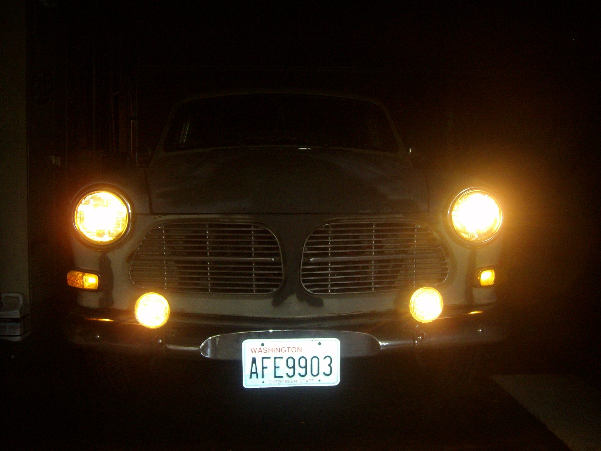
Turn on the ignition and hit your switch. Nothing should happen. Now, turn on your headlights to “low beam” and the fog lights will come on. Toggle the switch and see that the lights work properly. Use lock ties to secure all wires.
You are now ready to move about the country! Your lights will penetrate the fog and… they look “racer cool.”
By Ric Glomstad